Wiring
At the first glance wiring can seem quite difficult, but when you get to look at the wiring almost all Lambrettas follow the same familiar colour coding. If you break the wiring down into sections, it becomes easier still!
![]()
![]()
Scope
With more and more machines becoming non standard in terms of parts fitted and used, the old wiring diagrams mean less in terms of how your scooter needs to be wired. In most cases now, you can pretty much follow the "lambretta family" of colour coding for wiring. So instead of making copies of wiring diagrams you can find in books, and all over the internet, we have choosen to try to make things a touch easier! Having said that, you should still be able to follow these instructions!
We will follow Series one, two and three Lambrettas as these are by far the most comon machines people use as a base for restoration / custom etc, if there is enough requetss I will go on and do others. As with my opening statement, if you are carrying out an "anorak restoration" with all original electrical components, swithes, loom, lights etc, then make note of connections, or get your self a copy of some material I have mentioned, books, etc, as for on here we will follow what colours appear on parts you buy today!
To make matters simple and easy to follow, we will seperate the wiring into the following:
• Front will be the headset,
• Rear will be the junction box on the frame leg
• Other will be rear light and brake switch.
FRONT
On the whole the front can be divided into two sections in terms of machines and what they use :-
Section one covers Li 125 /150 S1, S2, S3, and many Servetas.
These are machines whereby all lights are controlled by the handle bar switch, and the igntion is controlled by a kill button or an on/off switch. It is worth noting that if like many you convert your kill button by to use of an on off switch from a Lambretta igntion switch, you are not affecting the way the lights operate, and so any switch you buy and use will not like other models under section two, control the lights.
Section two covers TV 175S2, and then most series three models Li Special, TV, SX and GP.
These are machines whereby all lights are controlled by igntion switch and then only high/low beam and the horn are on the light switch itself
Section One
Li 125 /150 S1, S2, S3, and many Servetas.
The following diagram may not represent your machines bulb holder, for instance series 1 and 2 Li models have a seperate junction box, and bulb holder, where as Series 3 Lambrettas bulb holders also combine the junction box. Whether seperate, or combined, the junction boxes are merely a means of connecting two wires together for most connections, the only diverstion from this is lights & earth which must be plugged into the correct holes. Some junctions connect their wires together by plugging one wire in the top terminal, others go side to side, but if you look at the back of your junction box it will become clear which way yours connect if you look at the joins between the terminal holes.
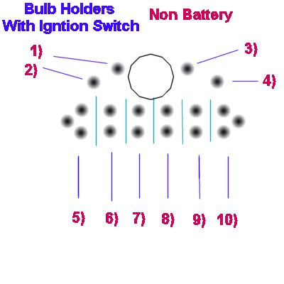
Please bear in mind what we have said about S1 & 2 machines which have seperate bulb holders to junction boxes, in these cases numbers 1, 2, 3 & 4 will be on the bulb holder, numbers 5 through to ten will be the junction box itself.
1. Blue Is for the main bulb, in reality it does not matter if you get number one and two mixed up, as one controls high beam, and one controls low beam on the main bulb. So for our sakes, plug the blue from the light switch to this.
2. Red As above, plug the red wire from the light switch here.
Handy Hint ** Dont touch the glass of Halogen bulbs with your bear hands it will cause premature failure of the bulb. If you do clean it with metholated spirits.
3. Yellow is for the pilot light, can also be called side light or city light! The yellow wire also comes from the light switch.
4. White This is for earth, on all original Lambrettas the earth wire will be attached to the headlight rim. It is much better to discard this and make yourself a new earth, the best place for this is on the headset rod stirrups. There are two either side, near the throttle or gear cable wheel, make a wire with a ring terminal on one end, secure by the screw holding the stirrup, and the other a bullet terminal which plugs into the junction.
Handy Hint ** It is important you do not get this mixed up with the earth side and yello feed side. Either check the colouring coding on the bulb holder, or look where the main bulb actually fits, down the side is an earth leg that sits against the side of the main bulb. Follow that tag, it will join either terminal 3 or 4, which ever one it does, thats your earth!
5. Leave blank (unless using electronic wiring loom).
Handy Hint ** Numbers 6, 7, 8 & 9 dont really matter which terminals they go in, they are merely and means of joining two wires together, so in matters not which colours go where, but it does matter that colour to colour connections are observed.
6. Brown Brown from the wiring loom, to brown on the light switch.
7. Green Green from the wiring loom to the wire from the cut out switch.
Handy Hint ** If you use a Lambretta igntion switch instead of a cut out for a touch more security, you need to connect the green from the switch, and then earth the pink.
8. Purple Purple from the main loom, to purple on the light switch
Handy Hint ** If you have an electronic wiring loom you will not have a purple. If this is the case, connect the two browns we mentioned for terminal 6 into terminal 5 instead. Then connect the purple from the light switch into terminal 5 also
9. Grey If your scooter is a battery model then grey from the main loom, to grey of the light switch.
10. Black Wires You will that three wires plugging in here, these control the rear light and speedo bulb. One black wire comes from the light switch, one black wire comes from the main wiring loom, the other black wire (normally black) will come from your speedo bulb holder.
The only thing left is to wire the horn. From the light switch will be a white wire, take this down to one terminal of your horn. On original looms the power feed for the horn will come out of the loom lower down near the horn, plug this in the circuit is complete. Where you do not have this power lead, take a wire and connect it to the brown wire, then take that wire down to the horn.
Section One
TV 175S2, and then most series three models Li Special, TV, SX and GP
1. Blue Is for the main bulb, in reality it does not matter if you get number one and two mixed up, as one controls high beam, and one controls low beam on the main bulb. So for our sakes, plug the blue from the light switch to this.
2. Red As above, plug the red wire from the light switch here.
Handy Hint ** Dont touch the glass of Halogen bulbs with your bear hands it will cause premature failure of the bulb. If you do clean it with metholated spirits.
3. Yellow is for the pilot light, can also be called side light or city light! The yellow comes from the igntion switch.
4. White This is for earth, on all original Lambrettas the earth wire will be attached to the headlight rim. It is much better to discard this and make yourself a new earth, the best place for this is on the headset rod stirrups. There are two either side, near the throttle or gear cable wheel, make a wire with a ring terminal on one end, secure by the screw holding the stirrup, and the other a bullet terminal which plugs into the junction.
Handy Hint ** It is important you do not get this mixed up with the earth side and yello feed side. Either check the colouring coding on the bulb holder, or look where the main bulb actually fits, down the side is an earth leg that sits against the side of the main bulb. Follow that tag, it will join either terminal 3 or 4, which ever one it does, thats your earth!
5. Leave blank (unless using electronic wiring loom).
Handy Hint ** Numbers 6, 7, 8 & 9 dont really matter which terminals they go in, they are merely and means of joining two wires together, so in matters not which colours go where, but it does matter that colour to colour connections are observed.
6. Brown Brown from the wiring loom, to brown on the igntion switch, this is the main feed for the lights
7. Green Green from the wiring loom to the green wire from the ignition switch. This controls ignition.
8. Purple Purple from the main loom, to purple on the igntrion switch, purple is an auxilary power feed.
Handy Hint ** If you have an electronic wiring loom you will not have a purple. If this is the case, connect the two browns we mentioned for terminal 6 into terminal 5 instead. Then connect the purple from the light switch into terminal 5 also
9. Orange Orange from the igntion switch to orange on the light switch, provides main beam power for the light switch to swap between high/low beam.
10. Black Wires You will that three wires plugging in here, these control the rear light and speedo bulb. One black wire comes from the light switch, one black wire comes from the main wiring loom, the other black wire (normally black) will come from your speedo bulb holder.
The only thing left is to wire the horn. From the light switch will be a white wire, take this down to one terminal of your horn. On original looms the power feed for the horn will come out of the loom lower down near the horn, plug this in the circuit is complete. If this is not the case, on most Indian made ignition switches the brown will have an extra spur wire, this can then go to the horn to provide power. Where you do not have either of these power leads, take a wire and connect it to the brown wire, then take that wire down to the horn.
You have finished the headset, move onto the Rear section.
Section Two
REAR.
The rear is much easier to work out, but is split into more differing machines. With many Lambretta owners converting to some form of electronic igntion set up, you should consolt the instructions that came with your kit to wire these up.
Most Lambrettas follow the same format when it comes to the junction box, colour goes to colour.
• Green plugs to Green
• Brown plugs to Brown
• Purple plugs to purple
• Pink to Pink
Models to differ are mainly either earlier four pole stators or battery stators. In this case the all follow.
• Green plugs to Green
• Brown plugs to Brown
Then depending on the stator you will have a choice of the following
Battery. Two yellows from the stator plug together, the grey and red from the main loom plug together. The two yellows provide the trickle charge for the battery, the red takes this charge to the battery, the grey takes the battery power up to the headset.
Four ploe stators differ depending on what make they are, but most will have a purple. This purple plugs to the purple in the main loom. It is worth noting on stators such as Dansi they have a blue, this blue must plug to its correct terminal if using the original junction box, if not it must go to earth somehow.
Section Three
Rear light and Brake Switch
Rear light is very easy, Pink is brake light, Black is rear light, the earth wire for the rear light should be in place which fixes to the bolt that secures the rear light housing. Please note it is a requirement for the MOT for all scooters no matter what year to have a rear brake light. On models where this is not fitted, you must fit a brake light. There is on way round this, you can apply for a daytime MOT, which means you should legally only ride your scooter in daylight, and you would not be allowed on the road after dark or in poor visibilty.
Brake light There are three types of brake light for Lambrettas, one wire, two wire or three wire. If you are changing your wiring loom, most modern looms come with two wires, in this case just fit a two wire switch. If you use an original loom, or a new but original loom, you will also need to match the amount of wires on your loom, to the appropriate switch.