Fitting electronic Ignition Kit
Fairly easy job to complete, you will need the following tools. Flywheel removal tool, flywheel holding tool, non powered timing light, wiring crimpers, spanners, sockets and screw drivers. An ohms meter is also very handy for checking and or fault finding the stator plates.
![]()
![]()
Scope
There are two types of crank taper, Li S1, 2 3, , Li Special, TV and SX models all share the same taper and so use an Li/SX electronic kit. The GP has a thicker taper and uses its own kit, make sure you buy the correct one from your supplier. All electronic igntion kits originate from India, and as such there can sometimes be varying qualities of kits supplied, but if you follow the instructions carefully you should be OK.
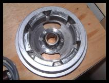
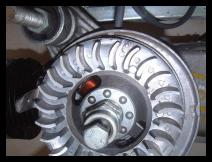
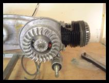
The first job is to remove the original flywheel and stator, remove diode + battery (if fitted) and H.T. coil.
Most Kits consists of:
Flywheel, stator, regulator, C.D.I. unit.
Fitting instructions:
If you do not have any of these components, you will need them! Some suppliers say you will also need an electronic loom, in truth this is not the case you can easily modify your existing loom. An electronic loom is pretty much a standard wiring loom, there is no difference in the core of the wires, there is simply one wire taken out and then two wires are slightly longer with different terminals on them. If you want to convert your battery equipped scooter to an electronic kit with battery, you need to retain a battery loom.
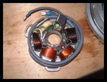
Depending on where you purchased your kit, you might need to check and inspect your stator plate, for more details on this please refer to our Electronic ignition fault guide In particular the hieght of the green wire, and the condition of the soildering for the wiring, this can be checked by a continuaty meter.
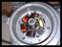
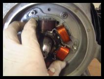
Most suppliers recommend fitting the stator in a central position on the oval holes of the stator plate, (unless of course you removed and marked an existing set up), this allows you to turn the stator either way to adjust the timing if needed. Just nip the nuts/bolts at this stage as you will almost certainly will need to move the stator around.
Thread the wiring from the stator through the whole at the top, taking note of the gap on the stator to allow the wires to sit into when fitted. Make sure you do not snag the wires when fitted, there is a plate to hold down the wiring that should be fitted to the top nut/bolt when securing the stator. With this tag it is a good idea to use something to knock it down, as the flywheel can catch this if it is not fitted properly, or far enough down. To secure the wiring, a gasket, two plates and a rubber grommet are used. The plates have a tapered side to them, after you have fitted the gasket to the engine casing, the first plate (they are the same) goes with the highest side in towards the engine, then the grommet, then the last plate with the raised part facing out. Secure the plates with two bolts, original ones were a screwdriver fit ment ones, for each of removal/fitting in the future you can use either Allen headed or spanner headed bolts.
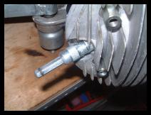
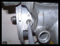
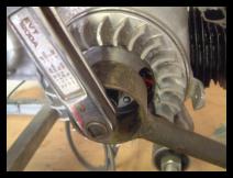
We are gowing to need to find TDC (Top Dead Centre) this is the point when the piston is in its highest point in its travel, up to the head. We are looking for when the piston will not go any further up, but not starting its travel downwards either. If you have a play, you will find a small point where the piston no longer moves. We are using a TDC tool, the outer part of it is used like a spark plug, simply screw it into the plug hole. It then has an inner rod, that you can rest on the top of the piston to give you better sight of its travel.
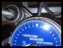
Now using our dial gauge, we need to measure the firing point. Take the flywheel back off, line the arrow on the dial gauge, it is in position zero degrees, with the mark you made on the mag housing with your screw driver. To do this there is a hole in the centre of the gauge, place this over the shaft of the crank, and lightly fit the nut back on with your hand, this insure more accuracy.
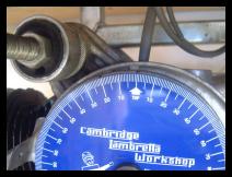
Timing is before TDC on all models, so to mark the firing point you will need to go back towards the engine mount from the zero position. Timing for models is 23 degrees Li/TV/SX and 21 degrees for GP, although with modern fuel most now recommend retarding the igntion by 2 degrees which would give 21 for Li/Sx and 19 for GP. If you have a performance kit fitted, you should check the required timing with your supplier. Again it is a good idea to make a second mark on the mag housing now with either using a dab of white paint (Tipex is good for this) or hammer & screwdriver to show the firing point. If using the hammer / punch method make sure the marks you make do not protude pieces of metal towards the flywheel which can cause it to rub. Making these marks will save you time if you need to set the timing up again from having to go through this again

Before you fit the flywheel properly, put the flywheel on with a new woodruff key, and rotate it by hand very slowly. We are doing this to make sure nothing catches or grinds. Keep repeating this excerise when the flywheel is tighten, and again when you torque the flywheel on at the last stages (see below)
Next tighten the flywheel nut, note it has left hand thread, it does not need to be particularly tight at this stage, just nip it up.
On the black box on the stator picture we showed earlier, we mentioned the white line. This white line needs to line up with two very small marks situated either side of a flywheel window, they are directly opposite each other in the same window.
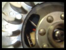
What we need to do its make sure when the arrow of the flywheel is lined up with the mark you made for your firing point on the mag, that the two lines on the flywheel window are in a perfect line with the white line of the pick up box.
If you cannot get them to all align, this is when you need to move the stator around on its oval holes to achieve this position. Undo the three bolts, rotate the stator slightly and try again. When you have done so, timing is intially set, and then only needs checking with a strobe when the engine is runing.
When you have set the timing by the marks on the flywheel, using a torque wrench tighten down the flywheel and torque to 50lbs. This figure is crutial on the Lambretta, never fit a flywheel without using a torque wrench Too loose the flywheel could fall off, to tight you could split the centre boss on the flywheel. Failure to use a torque wrench is probably the single most comon cause for flywheel problems, and almost certainly as well as invalidating your warrenty, will give you problems with your kit.
The use of cheap un powered strobe lights is recommended, as self or battery powered timing lights can give false readings. With the engine running, point the timing light at the firing point mark, you should see the arrow of the flywheel opposite it. If the arrow appears to the left or the right of the firing point mark, the kit has a slight manufacturing defect (which is more then normal), and you should re adjust your stator plate. Continue to double check with the strobe light until the arrow of the flywheel is directly opposite the firing mark.
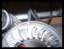
To aid cooling of the engine you can at this stage nibble away the outer lip of the mag flange with a pair of pliers. I refer to the lip that fits into the outer section of the original flywheel. Remove material only from the front section (nine o'clock). This is not absolutely necessary, but advisable if the engine is driven continually at maximum speed.
Fit flywheel dust cover and circlip. Secure flywheel cowling.
Continuation of assembly
You will need an electric drill and 1Omm mounting bolts.
Fit junction box to the nearside footboard frame leg. Fit H.T. lead to C.D.I. unit.
Secure the regulator C.D.I, unit somewhere close to the junction box. Make sure that the regulator is well earthed and solidly mounted. It must not be near any heat source. Take the earth wire for the C.D.I. unit and secure under one of its mounting bolts or another suitable earth position.
Wire up regulator and C.D.I. unit as per diagram. Tate original green wire that went to the H.T. coil, fit with the Lucar terminal supplied and fit to the C.D.I, unit.
Take the wires of the main wiring loom and push into junction box (anywhere), except for the two green wires (joined), which must go into its respective green hole, or the two greens can be taped, but in no way come into contact with the lighting circuitry.
Take a yellow wire and push into the junction box. and then to the regulator (G), as per diagram.
Fit the another wire as an earth wire for the regulator.
If the original machine was fitted with a battery then tape up the battery feed wires, If your machine was previously fitted with 6 volt bulbs then replace with 12 volt ones. If your machine was previously D.C. (with battery) you will also need to change the horn to an A.C. type.
Check for spark, start engine and check lights.
The C.D.I. unit and regulator used on this A.C. conversion are the same as those fitted to the Vespa PX.
Wiring Diagrams / help continued
You should follow the instructions that come with your kit (if you do not recieve any, complain to your supplier, they should really supply some!!) as some wires differe depending on origin of manufacture. On the whole, many electronic kits follow the colour coding as below, but if in doubt check!
Below we show three diagrams, the first is for a standand non battery instalation, as this is the most comon way of supplying an electronic. You can however make use of a battery regualtor, which you may have to purchase seperatly, to allow the use of a battery on your scooter. There are two ways to use a battery, if your scooter is a battery model already, you will already have battery switches / igntiions in place, so simply change the bulbs, battery and horn to 12v items and follow diagram 2. If you want to add a battery to a non battery system, to convert to original specification battery model you will need to change the wiring loom, ignition switch (if fitted) and light switch. In most cases this is not worth while due to costs. However to supply power to a battery to run such accessories as lights, horns etc, then you an follow diagram three, and then power your accessories from the battery.
Where the diagram shows original wiring loom, observe the following. On original non battery looms, connect the brown, purple and pink together and connect to the output terminal of the lighting regulator. For the green, the original coil wire has a round terminal on it, cut this off and fit a spade terminal and plug this into the terminal marked green on the CDI unit. Make sure the original double green in the junction box is made safe and not connected to any other wires or to earth.
Figure Two, original battery set up
Where the diagram shows original wiring loom, observe the following. On original battery looms, connect the brown and purple together and connect to the output terminal of the lighting regulator. Connect the red and the grey together and connect to the terminal marked B+. For the green, the original coil wire has a round terminal on it, cut this off and fit a spade terminal and plug this into the terminal marked green on the CDI unit. Make sure the original double green in the junction box is made safe and not connected to any other wires or to earth.
Figure Three, auxilary battery
On machines where you want to provide an auxillery battery, ie you only want to charge a battery from the scooters electrics, and then wire up accessories using power taken from the battery, follow the instructions for non battery. The only other thing you need to do is take a wire from the B+ terminal of the regulator to the + positive side of a battery. Earth the negative - pole of the battery to the scooter frame.