 |
Putoline Oil is an important player in the market for motorcycle lubricants and maintenance products |
Full Engine Re-Build
We would first like to thank Rick Huggins for putting together this article for us all to learn a trick or two from.
Whilst we have given this job a five spanner rating, you should not let this put you off. As long as you are methodical and particular in the way you check items, you should be more then capable of stripping and rebuilding your engine given time and the right tools!
Tools you will require are :- Flywheel puller, flywheel holder, clutch compressor, clutch holding tool, T bar extractors (or 2x long M6 bolts), circlip pliers, a source of heat such as a heat gun, spanners, socket set, screw drivers.
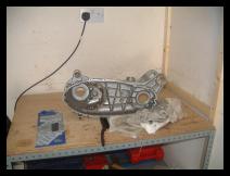
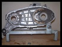
For the purposes of our engine rebuild, we have started with a bare Indian casing. If you need to strip your engine, it is fairly straight forward, but should you need help with a particular part you can always read this article backwards! You can of course just as easily strip and rebuild the entire Lambretta engine with it in the frame. Personally as long as you have a bench to raise the scooter to an accetable level I find that leaving the engine in the scooter can be easier. Each to their own though, as some prefer the engine on a bench. Either way you use, make sure you have plenty of light, access to all sides of the engine/scooter and most importantly be relaxed! Taking your frustations out whilst working on an engine will result in breaking something you shouldnt.
On our new casings, some of the casting marks can still be found from the moulds, and even if you are using your one that you have just stripped, the first job will be to clean and inspect everything. Jizer, Gunk or some people even have their casings bead or vapour blasted, but what ever you choose, the casings are pretty soft alloy, don't get them sand blasted or similar as you will ruin them. Acid dipping has also been know to be done, but this can affect the castings so be careful.
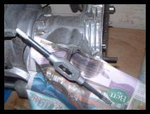
With the casings totally bare, and even on our new casings the first thing to do is check all stud holes, a tap is being used here just to clean the thread. Where needed alloy welding, re drilling and tapping new threads is the first job. There is nothing worse then building the whole engine only to find a thread has gone, which if welding is needed, a total strip back down is more than likely needed.
Points of wear on the casings are stud holes, where the mag housing goes in, bearing and crank housings, and check where the end plate bolts go in on the outside. The seat of the endplate and in particular the studs/holes need careful inspection. With all stud holes repaired, to do this time inserts are best, Wurth do make some very good ones, but they are expensive! Helicoils are a cheaper alternative, but you should note that they are not always a suitable repair on items that need high torque settings, or are removed and refitted often.
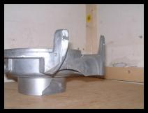
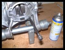
OK ready to start getting dirty? First of all, I always try to work as cleanly as possible, sure you will get dirty hands, but wash them often and carry on. Engine mounts are to be taken out and refitted first, the best way to do this is with an engine mount removal/refitting tool. These can be expensive, so if you are buying a new casing, it may pay you to ask your supplier to fit the mounts for you, or ask a friend to borrow their tool. You can fit these with heat and two hammers, but unless you know what you are doing with this method, the best answer to this is dont!
The method mentioned above using two hammers, when not using the special tool is to support the back of the casing with a large pound hammer, copper grease the mountings to help them slide in, gently heat the casing where the mounts go then from the front knock the mountings in. It is of course very easy to break your casings when using this method, and where ever possible you should use the correct tools for the job. Take note on the large mounts there are three holes in them, these holes should be pointing forwards.
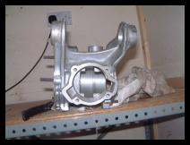
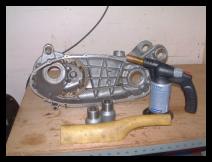
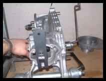
Now we have the mounts in, we are fitting the engine to a special tool, the engine case holder just to make our life easier when moving the casing around, again this is not needed but helps when the casing is out of the scooter frame.
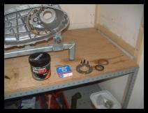
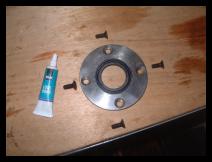
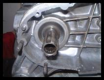
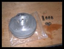
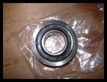
Here we are starting with the drive side bearing set up, shown are the parts needed to fit the bearing. Good quality grease, drive side bearing, halotite gasket, oil seal and plate, plus four retaining bolts.
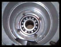
There are three methods to fit the drive side bearing, heat the casing by means of blow torch or similar, freeze the bearing as it makes it shrink, or buy a bearing press tool. There are manufacturers of tools specifically for Lambretta, if your going to make a habit of doing these jobs they are well worth the expense. Using one of these methods, press the bearing into the engine casing, it does not matter which way round it goes, but it is important that it is pressed all the way home. You can check this by looking at it through the chain side of the casing, it should fit right up tight against its housing. If using the heating or freezing method, be sure to use a suitable drift that fits the outside of the bearing, not the rollers or inner track, otherwise you will damage the bearing.
Once the bearing is pressed home, you can smear the balls of the bearings with high melting point grease, this will help the bearing whne you first start the engine.
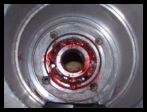
The round gasket is then fitted, some gaskets will not fit this housing perfectly, do not worry, just simply and carefully push the gasket edges into the housing with a flat screwdriver, just be careful when doing this. As with all gaskets, a thin smearing of grease over both sides will make the gasket supple and easier to fit.
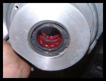
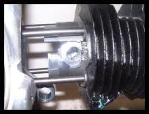
Next we need to fit the oil seal to the plate, the picture here shows the correct way round it goes. The spring around the oil seal should face the the crank when it is finally assembled. Four new screws are used, it's always best to use new ones here as the old ones almost certainly will be damaged when removing them. New ones from most dealers will now be supplied as high tensile Allen key headed bolts, it is much easier to secure and do this type of screw. Lock-tite is always sensible on these bolts.
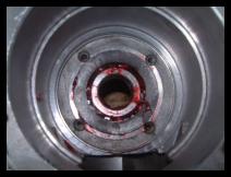
The plate is diagonally torque'd, this makes sure the plate sits down evenly, keep going around them until you are sure all four bolts are secured as tight as they can be, there is no torque setting for these bolts, but you should tighten them fully until they will turn no further. Once tightened, centre or dot punch on the outside of the bolt to the casing, this will ensure the bolts cannot losen themselves.
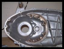
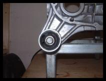
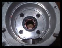
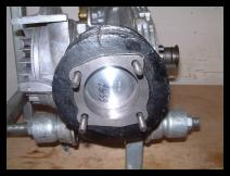
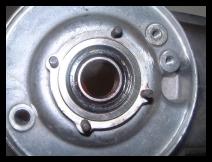
With this picture you can see that the oil plate is fitted correctly, it is vital that the plate is secured fully home and is flush as in the picture. If the plate sits proud and is not secured correctly, your crank will rub against it and not turn correctly, damage will occur.
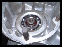
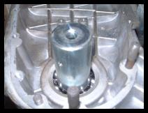
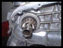
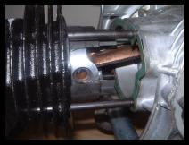
Place the mag or stator housing so that the inner part faces upwards. Now as with the drive side bearing you need to either heat the housing, keep the heat at the top of the housing. When heated, fit new seal carefully as the housing is hot! with spring facing towards you (it will end up facing into the crank when you have finished) Fit the L shaped cup washer next.
Now we need to fit the bearing, it comes in two halves, put the inner to one side as this must be fitted to the crankshaft. Either with your bearing tool or by using a socket or similar, make sure that what you use puts the pressure on the outer track, knock the bearing in position. Make sure it goes in square, tap it fully home. Li SX and TV models, if you are using the original size of bearing (NU205) fit the spacer washer. GP models and machines using a GP crank with the larger bearing (NU2205) do not have or use this spacer.
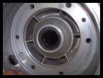
With the bearing in position, fit the last larger oil seal, again with the spring side facing you, towards the crank when assembled. A large circlips holds everything in place. Lightly pack the inner bearing with your grease as no oil gets here to lubricate it and it relies on this grease. With every thing finished your mag housing should look like this!
Preparing the new crank, if you are not re-fitting your old crank you will need to fit the new mag side bearing inner track. The easiest way to do this is using a proper bearing drift tool, or a deep socket. To ease the fitting of the inner track, you can always place your cranksafht in the freezer for a few hours, this helps to shrink it a touch. Support the crank, if using a vice, use the jaws on the taper side of the cranks web cheek only, this helps to avoid twisting or knocking your crank out of true. Tap home around the whole inner track to make sure it is seated properly.
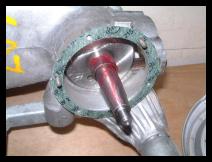
Fitting the crank, smear a little grease on the inner edge of the drive side oil seal, this helps the crank through, then by passing the shorter shaft through first, it is easier to get the crank at BDC, so the crank is at it's shortest. First smear a little grease on the drive side inner seal that we fitted earlier, a very slight coating is all that is needed. This helps the crank pass through it, less chance to nip the edge of the seal.
The crank to start with should be pushed as far as possible by hand, rotating the crank slightly as you go, again to make sure you do not snag the edges of the oil seal.
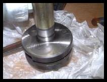
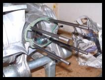
Here we are using a special tool to pull the crank through, from the chain side position the space central on the bearing.
The front sprocket bolt is used to pull the crank through into position. If you do not have this special tool, fit the flywheel nut on the end of the crank, this stops you from damaging the thread on the crank, and using a rubber or nylon hammer, gently tap home the crank, again rotating the crank as you go.
Here we can see again, the use of the tool to pull the crank through, we are also using a con rod holding tool to position the crank
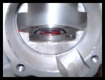
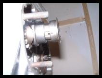
Note how the crank is fully home now, flush to the drive side plate, but still turning freely.
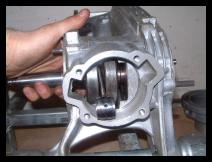
Before you fit the mag housing that we have built, the first step is the gasket for the mag flange, this will only fit one way, make sure all the holes line up with the gasket. Lightly working the gakset with a small smear of grease on your hands allows the gasket to become supple and allow it to work properly. This also helps when removing items, as light smear of grease should aid removal as well!
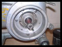
Fit the mag housing assembly, this should be a pretty good fit, wiggle it into position, if its a little tight, a rubber hammer gently tap it evenly around the edges until it is home. If you are using your original one, it will need cleaning to make it fit easier. Once the mag housing is just about home, three nuts on the studs secure this. Again in a diagonal pattern tighten this fully home. Finally check the crank still turns freely.
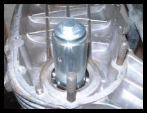
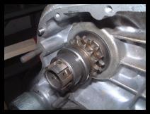
Now you have the mag fitted, we can turn our attentions to the front sprocket assembly
The dished washer goes on first, dished side down. One early series one engines they do not feature a resses for the washer as no washer is used.
The drive sleeve has splines on it, in no special way other than to match these splines with the splines on the crank shaft, fit the sleeve.
The front sprocket goes next, the half moon part of it faces out towards you.
Next the bottom spring collar goes on, but before you fit the spring, place the top collar on.
In this picture you will see, where the oil way hole is on the drive sleeve, we have used a felt pen to make a mark directly opposite this. This will help us line every thing up when we come to secure it all down. Take this top sleeve back off now you have made this mark
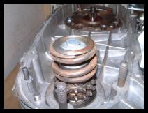
Fit the spring on next, and put back on the top collar, lining up the pen mark you made with the whole as best you can. Tighten the whole assembly down now, a note should be made that we still have our conrod holding tool in position to secure everything. If you do not do this it will be impossible to fully tighten the front sprocket bolt. Once you are happy that every thing is aligned with your marks, tighten home fully the front sprocket bolt. When complete it is important you double check every thing is correct by hitting the front sprocket assembly with a hammer, if it sounds solid every thing is correct, if it sounds hollow, take it off and start again!
Fitting of the new barrel studs is easily done by the double nut method. By this we mean screw one of the head nuts on to the stud, then screw another directly after it, lock them together with two spanners. Now using one spanner, if you have locked the nuts together tightly simply screw the bolts down with the spanner. Again with two spanners un lock these nuts and move on to the next stud
Carry on fitting and four studs, ideally we are looking to get them all the same height as far as they will go in. Fit your cylinder base gasket now, it will only line up and fit properly one way round.
Top Tip Vespa PX cylinder studs are ideal to use as they are slightly longer and will make sure you get enough thread of the stud into the engine casing.
Although we have fitted the cylinder and piston here, we are showing you this picture now for you to note the correct way round the piston goes, the arrows of the piston face to the exhaust port. The easiest way to fit the top end is to fit the piston and rings into the cylinder first. Fits both or all three rings (depending on your make of piston) on to your piston, making note as the rings have a cut out which fit into the peg on the piston one way only.
Compress the rings onto the piston while sliding into the barrel from the bottom, i.e. the top of the piston goes into the bottom of the barrel. Slide the piston up one ring at a time, each time making sure the ring has seated properly into the bore of the cylinder.
First fit the base gasket, again as with all gaskets lightly working some grease into it with your hands will help it to work properly. Slide the barrel on to the studs as in the picture above. Fit the small end bearing into the crank, it is a good idea to dip this in a little light oil or two stroke oil to aid in the first start up. Line the conrod and piston up so you can fit the gudgeon pin and tap through lightly with a rubber hammer. Fit both piston circlips, make sure they are fitted correctly by turning them in their grooves. If they do not turn easily or pop out, they were not seated correctly, try again.
Slide the barrel fully down the studs, if you are using a dial gauge to set top dead centre (TDC) now is the time to skip to the stator and flywheel section so you can mark TDC.
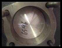
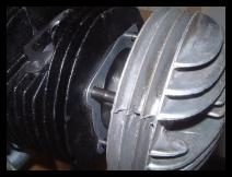
The cylinder head and parts needed to fit, notice the one nut longer then any other, this is used to secure the cylinder head cowl. If you are using your old cylinder head, it will need to be flatted, but you should also double check new cylinder heads as well! To do this, simply use a piece of glass and sticky back sand paper, grinding disc is ideal. rotate the head within your hands using a twisting movement 1/4 of a turn for ten times. Carry one after each ten twists by turning the head 90 degrees and doing again, you should end up doing this four times. Look at the surface where the gasket goes on, it should look like it has been sanded in all areas. If some areas are left untouched by the sand paper, the head is not flat and repeat the whole process until it is.
First fit your head gasket, then place your head on top of this. The head should only fit on the studs one way, the spark plug hole should be facing the top left hand side.
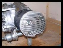
Again in this picture take note of the long nut that excepts the cylinder cowl bolt, because we have the engine on a stand, it is upside down, so yours again with the engine the correct way up should be on the bottom left hand stud as you look directly at it.
Finally in a diagonal pattern, it is important you torque these nuts down, the Lambretta Home Workshops manual does state 15lbs, but in truth 18 to 20 is better.
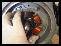
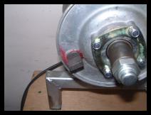
Carrying on at the top end, we are now going to fit our electric's. Here we are fitting an electronic kit, but roughly speaking the points and condenser stator are fitted in the same way.
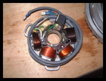
The electronic stator, the main difference is the "black box" pick up, it is at the top of the stator with a white line on it. If you are using the points/condenser type stator, you will of course need to almost certainly fit new points and condenser, check the workshop section for this.
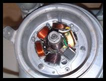
Thread the wiring from the stator through the whole at the top, taking note of the gap on the stator to allow the wires to sit into when fitted. Make sure you do not snag the wires when fitted, there is a plate to hold down the wiring that should be fitted to the top nut/bolt when securing the stator
I always recommend fitting the stator in a central position on the oval holes of the stator plate, unless of course you have marked the stator and housing before removal, this allows you to turn the stator either way to adjust the timing if needed. Just nip the nuts/bolts at this stage as you will almost certainly will need to move the stator around.
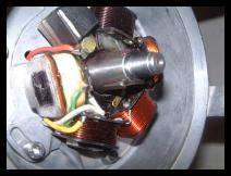
To secure the wiring, a gasket, two plates and a rubber grommet are used. The plates have a tapered side to them, after you have fitted the gasket to the engine casing, the first plate (they are the same) goes with the highest side in towards the engine, then the grommet, then the last plate with the raised part facing out. Secure the plates with two bolts, original ones were a screwdriver fit ment ones, for each of removal/fitting in the future you can use either Allen headed or spanner headed bolts.
Finally before you fit the flywheel, just make sure none of the wiring is to high and will catch on the flywheel. In particular check the wiring tag is in place and again, that it cannot be rubbed by the flywheel.
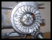
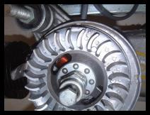
Next put the flywheel on, and tighten the flywheel nut, note it has left hand thread, it does not need to be particularly tight at this stage, just nip it up.
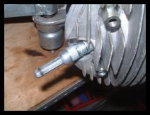
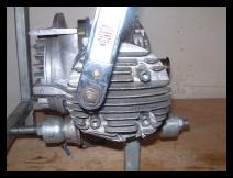
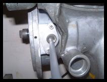
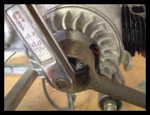
We are going to need to find TDC (Top Dead Centre) this is the point when the piston is in its highest point in its travel, up to the head. We are looking for when the piston will not go any further up, but not starting its travel downwards either. If you have a play, you will find a small point where the piston no longer moves. We are using a TDC tool, the outer part of it is used like a spark plug, simply screw it into the plug hole. It then has an inner rod, that you can rest on the top of the piston to give you better sight of its travel.
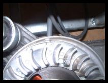
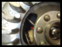
When you have found TDC, there is an arrow on the flywheel, we need to make a mark on the outer ring of the mag housing directly opposite this arrow, Using a bladed screwdriver and hammer, a gentle tap will be enough to cut a groove in the alloy. Take note again because of the holding tool our engine is upside down
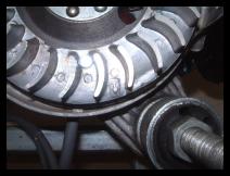
Now using our dial gauge, we need to measure the firing point. Take the flywheel back off, line the arrow on the dial gauge, it is in position zero degrees, with the mark you made on the mag housing with your screw driver. To do this there is a hole in the centre of the gauge, place this over the shaft of the crank, and lightly fit the nut back on with your hand, this insure more accuracy.
Timing is before TDC on all models, so to mark the firing point you will need to go back towards the engine mount from the zero position. Timing for models is 23 degrees Li/TV/SX and 21 degrees for GP. Again it is a good idea to make a second mark on the mag housing now with your hammer & screwdriver to show the firing point. This will save you if you need to set the timing up again having to go through this all the time.
Now this is where the points and electronic set ups differ. First I'll cover electronic, on the black box on the stator picture we showed earlier, we mentioned the white line. This white line needs to line up with two very small marks situated either side of a flywheel window, they are directly opposite each other in the same window.
What we need to do its make sure when the arrow of the flywheel is lined up with the mark you made for your firing point on the mag, that the two lines on the flywheel window are in a perfect line with the white line of the pick up box.
If you cannot get them to all align, this is when you need to move the stator around on its oval holes to achieve this position. When you have done so, timing is set.
To set a points system, follow the electronic instructions except. For this I use a battery and bulb & holder, attached one side of the bulb to an earth, the other to the battery, of which the other side of the battery wire goes to the green coming from the stator. Instead of lining the lines up, what we are looking for here is when you turn the flywheel to the firing mark, the bulb will become brighter when it reaches this mark exactly. Too soon or to late, you will need to either adjust the points on the screw, this is done by undoing the screw, turning the bottom plate of the points slightly, and nip back up and try again. If you cannot get the light to brighten by adjusting the points base, again moving the stator on the oval holes and try again adjusting the points further.
When you have finally set the timing, make sure the stator plate retaining bolts or nuts are tightened, again using a torque wrench fit the flywheel and torque to 50lbs. This setting, along with the rear hub, is the most important torque setting on a Lambretta, failure to do this can any mostly likely will result in major problems, you have been warned!
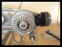
Job done, your top end is now complete, only thing left to do is fit the spark plug and cowlings. I always leave the cowlings until it is in the frame and every thing has been checked and the scooter is running. Just saves you time in case you got any thing wrong!
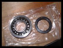
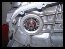
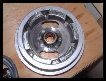
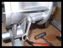
Turning our attentions to the rear end and gearbox of the scooter now, with the rear hub bearing and oil seal
Fit the oil seal into the bearing first, it should have the oil seal fitted into it with the springs facing into the crankcase.
You may need to heat the crank casing up to fit the rear hub bearing, some people prefer to freeze the bearing this makes it shrink. You can also of course use a bearing fitting tool for this job. Fit the bearing/seal into its recess in the crank case, it will only fit one way round, and it goes in from the brake shoe end. Pack with high melting point grease.
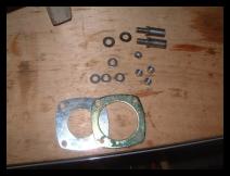
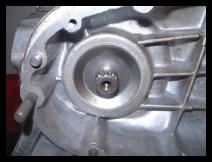
Here we have the parts to secure the bearing one thin shim plate, on thick but small retaining plate and four washers & nyloc nuts.
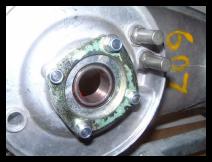
First slide the shim plate over the four studs, next the smaller but thicker plate, all held down with washers and nyloc nuts. Again do this up in a diagonal pattern, nice and tight. We have also while we are here, fitted the two rear brake shoe pivots, this end is now complete bar the brake set up.
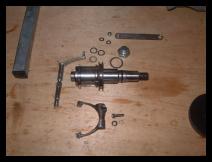
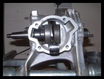
Here we see all the parts needed to fit the main shaft. The gear selector, selector shaft and seals. Fit the gear selector first on GP models this is one complete unit which includes the outer arm. On earlier models the selector arm is separate to the shaft, you just need to fit the shaft at this stage.
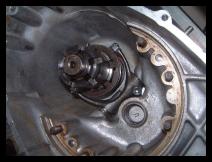
The sliding dog should be fitted to the lay-shaft first, to do this insert the selector spring in the centre of the layshaft, and hold a ball bearing at each end of this spring. If you look at the sliding dog at the end with the ring on, it has two recess to make fitting this assembly together easier. The feet of the dog should be flush with the end of the shaft (this is first gear). -fit the shaft through the bearing and make sure the lugs on the gear selector wishbone locate into the sliding dog
Tap the lay-shaft home with a hide mallet. Place the rear hub cone washer onto the lay-shaft then a suitable distance piece (avoids messing with the rear hub). Place the rear hub washer and nut then tighten, we will tighten it properly later on. If you cannot find a suitable spacer, simply fit the rear hub and toque. In both cases this is done to set the gearbox up correctly.
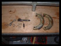
With the lay shaft in position we can Finish off the brake now, here you can see all the parts needed for the job, your shoes, clips and operating levers and shaft.
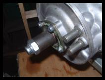
Fit the operating cam through the hole in the engine casing, grease this when fitting as it is important for a good operating brake.
Next fit the brake arm, notice the position it is in, it needs to be some where like this for the brake to operate correctly when you connect the cables up. The arm is held on to the shaft by a circlip.
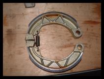
We are now ready to fit the brake shoes, you will find it much easier to fit the return spring to the two brake shoes first, expand the shoes or the operating cam, and then place the holes of the shoes by stretching them apart, on to the pegs you fitted earlier.
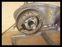
Finally fit the retaining W clip, sometimes you will be supplied or have two circlips with plates, either way is fine, and it does not matter which method you use.
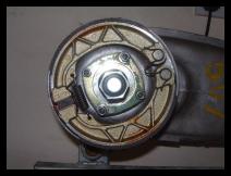
Finally before moving on, now is a good time to slip the rear hub on and check the brake shoes are not binding to the rear hub.
Twist the hub from side to side to see if it is free. If not, take the hub back off, and look for marks on the shoes. Flat these areas and try again, continue do do this until your shoes do not rub any longer. Often people moan and this and or blame pattern parts. As with any restoration you should expect a certain amount of fettleing to make parts fit. Lets face it even Innocenti made a brake shoe trimming tool for this job, so if genuine Innocenti shoes are not expected to fit straight out of the box, then neither should pattern parts. A good way of taking some material off the shoes is to get a strip of emery cloth, hold it each side of the shoe and rub the shoes all over. This ensures an even surface on the shoes, and that the brake should not need major adjustments once bedded in. Whilst you are there, take the rear hub, whether old or new, and rub the braking surface of the drumn with the emery cloth. This deglazes the drum, and ensures a good surface for the shoes to grip, thus better stopping power. If you consult most major manufactueres instructions, they do infact include this deglazing of braking surfaces for brake shoes/drum at least annually, you Lambretta will benefit also from carrying this out.
Continued...