Hi, I've tried doing a search but can't quit find what I'm after so here goes.
I did find on here To use a LED headlight I have to go from A/C to D/C. Is this as simple as fitting a 4 way bridge rectifier to the high and low beam wires from the switch and then onto the bulb holder ie AC in DC out and then fitting a capacitor to the DC side to take out the micro flickering thus making the light brighter?
This would then lead me to asking which type of bulb will give a focused pattern?
Like I say I've looked on here so I'm not going along the path of not doing the searching. Thanks
LCGB Forums
The ability to post messages is restricted to LCGB members. Any questions contact us at lcgbadmin@googlemail.com
How easy to go to dc lighting?
12 posts
• Page 1 of 1
How easy to go to dc lighting?
![]() by Thackers » Sun Sep 22, 2024 12:46 pm
by Thackers » Sun Sep 22, 2024 12:46 pm
- Thackers
- Posts: 257
- Joined: Fri Jan 22, 2016 11:40 pm
Re: How easy to go to dc lighting?
![]() by Fast n Furious » Sun Sep 22, 2024 7:41 pm
by Fast n Furious » Sun Sep 22, 2024 7:41 pm
The LED bulbs that I recommend can be found here.
https://www.dynamoregulatorconversions. ... =161255034
These are a well made "angel eye" style LED bulb that will focus the dip beam where you need it (and its adjustable via a small allen key) and it doesn't require a tip top reflector.
To eliminate the flickering at tickover, you would only need a single 10amp diode in series with the output wiring from your regulator with a 4700uF/100v electrolytic capacitor connected across the output side of the diode and chassis. This will supply DC to everything so you may have to change your horn.
Else...... you could just connect the diode in series with the wire that supplies your dip/beam switch. The capacitor can be held in place inside of the headset with a bit of velcro. This would then supply DC to the headlamp only.
-

Fast n Furious - Posts: 1750
- Joined: Sat Nov 19, 2016 3:56 am
- Location: York
Re: How easy to go to dc lighting?
![]() by Thackers » Sun Sep 22, 2024 11:59 pm
by Thackers » Sun Sep 22, 2024 11:59 pm
Thank you for the reply and link, ill be sure to study all the info. This might sound a bit thick as i'm no electrician but what do you mean by " In series" Thanks again 
- Thackers
- Posts: 257
- Joined: Fri Jan 22, 2016 11:40 pm
Re: How easy to go to dc lighting?
![]() by dickie » Mon Sep 23, 2024 7:57 pm
by dickie » Mon Sep 23, 2024 7:57 pm
Fast n Furious wrote:The LED bulbs that I recommend can be found here.
https://www.dynamoregulatorconversions. ... =161255034
These are a well made "angel eye" style LED bulb that will focus the dip beam where you need it (and its adjustable via a small allen key) and it doesn't require a tip top reflector.
To eliminate the flickering at tickover, you would only need a single 10amp diode in series with the output wiring from your regulator with a 4700uF/100v electrolytic capacitor connected across the output side of the diode and chassis. This will supply DC to everything so you may have to change your horn.
Else...... you could just connect the diode in series with the wire that supplies your dip/beam switch. The capacitor can be held in place inside of the headset with a bit of velcro. This would then supply DC to the headlamp only.
Pete, why do u think a diode is sufficient rather than full wave rectifier?
- dickie
- Posts: 1907
- Joined: Thu Oct 02, 2014 12:32 pm
- Location: Tyne and Wear
Re: How easy to go to dc lighting?
![]() by Fast n Furious » Mon Sep 23, 2024 11:40 pm
by Fast n Furious » Mon Sep 23, 2024 11:40 pm
Unlike so called "DC stators", "AC stators" have one leg of the lighting coil pack connected to ground. So you can't use a bridge rectifier to create full wave rectification here cos the -ve point would share the same connection with the AC lighting coils!
The "AC" regulator, is primitively constructed using only a zener to half wave rectify and clip the peak voltage to around 17v p/p.
Add in an extra diode by cutting the wire in the headset that feeds the dip beam switch (orange on most series 3 and GP) and connect in the diode here. (make sure to get it the right way around) and also solder in the capacitor.
Connect the +ve side of the cap to the -ve side of the diode (cathode) ( Thats the end of the diode with the round band on it if you are using a typical in-line package diode) and also connect this to the dip switch side of the orange wire.).
The -ve side of the cap then needs to connect to chassis.
The loom(supply) side of the cut orange wire now connects to the Anode side of the diode.
This "In series" diode (SR5100 is recommended. Easily avaialable on fleabay) is really only there as a blocker to stop the cap from discharging back into the lighting coils, therefore providing a smoothed DC voltage to the headlamp bulb only.
With an LED bulb, I think 4700uf should be enough but if the lamp still flickers to an unacceptable degree on tickover, then a higher capacitance may be needed.
You'll also need some extra bits of wire for the capacitor connections and some heatshrink tubing to finish the job off properly.
( remember to slide your heatshrink tubing onto the wires first before making your soldered connections. Arrrgh )
) 
Btw.. Those bulbs that I recommended work from 6v-24vDc.
The "AC" regulator, is primitively constructed using only a zener to half wave rectify and clip the peak voltage to around 17v p/p.
Add in an extra diode by cutting the wire in the headset that feeds the dip beam switch (orange on most series 3 and GP) and connect in the diode here. (make sure to get it the right way around) and also solder in the capacitor.
Connect the +ve side of the cap to the -ve side of the diode (cathode) ( Thats the end of the diode with the round band on it if you are using a typical in-line package diode) and also connect this to the dip switch side of the orange wire.).
The -ve side of the cap then needs to connect to chassis.
The loom(supply) side of the cut orange wire now connects to the Anode side of the diode.
This "In series" diode (SR5100 is recommended. Easily avaialable on fleabay) is really only there as a blocker to stop the cap from discharging back into the lighting coils, therefore providing a smoothed DC voltage to the headlamp bulb only.
With an LED bulb, I think 4700uf should be enough but if the lamp still flickers to an unacceptable degree on tickover, then a higher capacitance may be needed.
You'll also need some extra bits of wire for the capacitor connections and some heatshrink tubing to finish the job off properly.
( remember to slide your heatshrink tubing onto the wires first before making your soldered connections. Arrrgh
Btw.. Those bulbs that I recommended work from 6v-24vDc.
-
Fast n Furious - Posts: 1750
- Joined: Sat Nov 19, 2016 3:56 am
- Location: York
Re: How easy to go to dc lighting?
![]() by Thackers » Tue Sep 24, 2024 11:38 pm
by Thackers » Tue Sep 24, 2024 11:38 pm
Thanks again for a really helpful reply. I'm going to look into doing this probably over winter. I think I have the idea of what you describe and want to take your advice with the bulb but they are a bit pricey at £40 odd for one, but sometimes you get what you pay for.
- Thackers
- Posts: 257
- Joined: Fri Jan 22, 2016 11:40 pm
Re: How easy to go to dc lighting?
![]() by Thackers » Sat Mar 01, 2025 5:58 pm
by Thackers » Sat Mar 01, 2025 5:58 pm
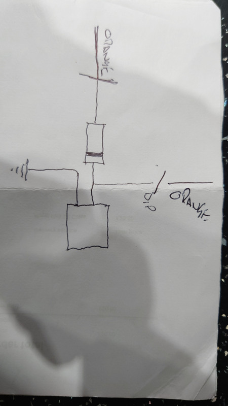
So, I'm finally getting round to trying to sort my lights  is the attached diagram I've drawn the correct plan to achieve what has been explained in the previous reply? Thanks.
Be kind as I'm no electrician, but willing to have a go and learn a little
The box on the diagram is the capacitor
https://i.postimg.cc/1RNqtYQS/20250301-164157.jpg
Be kind as I'm no electrician, but willing to have a go and learn a little
The box on the diagram is the capacitor
https://i.postimg.cc/1RNqtYQS/20250301-164157.jpg
- Thackers
- Posts: 257
- Joined: Fri Jan 22, 2016 11:40 pm
Re: How easy to go to dc lighting?
![]() by Fast n Furious » Sun Mar 02, 2025 12:58 am
by Fast n Furious » Sun Mar 02, 2025 12:58 am
Yes.
Just remember to make sure that you connect the capacitor up the correct way around. (-ve of the cap to chassis and +ve to the cut orange wire leading to the dip/beam switch.)
Just remember to make sure that you connect the capacitor up the correct way around. (-ve of the cap to chassis and +ve to the cut orange wire leading to the dip/beam switch.)
-
Fast n Furious - Posts: 1750
- Joined: Sat Nov 19, 2016 3:56 am
- Location: York
Re: How easy to go to dc lighting?
![]() by Thackers » Sun Mar 02, 2025 10:22 am
by Thackers » Sun Mar 02, 2025 10:22 am
Fast n Furious wrote:Yes.
Just remember to make sure that you connect the capacitor up the correct way around. (-ve of the cap to chassis and +ve to the cut orange wire leading to the dip/beam switch.)
Brilliant, thank you for your replies and help, I really appreciate your time and advice which I followed and bought one of the bulbs you suggested.
- Thackers
- Posts: 257
- Joined: Fri Jan 22, 2016 11:40 pm
Re: How easy to go to dc lighting?
![]() by coaster » Tue Mar 04, 2025 1:39 am
by coaster » Tue Mar 04, 2025 1:39 am
I've been using the Wassel Rectifier/regulator method for several years with no issues. I also use a Jockeys H4 headlamp and a cheapish (£15) led off ebay which is giving a fantastic beam and light coverage as good as the HID lamp that it replaced.
-
coaster - Posts: 2714
- Joined: Fri May 30, 2014 1:00 pm
- Location: Norfolk, Flying 8 Balls
Re: How easy to go to dc lighting?
![]() by Thackers » Wed Mar 05, 2025 1:12 am
by Thackers » Wed Mar 05, 2025 1:12 am
coaster wrote:I've been using the Wassel Rectifier/regulator method for several years with no issues. I also use a Jockeys H4 headlamp and a cheapish (£15) led off ebay which is giving a fantastic beam and light coverage as good as the HID lamp that it replaced.
Have you got a link to the Ebay item please? I'm thinking if I can do this I might try it on my other scoot which I don't use as much
- Thackers
- Posts: 257
- Joined: Fri Jan 22, 2016 11:40 pm
Re: How easy to go to dc lighting?
![]() by martyn dwane » Wed Mar 05, 2025 10:42 am
by martyn dwane » Wed Mar 05, 2025 10:42 am
everything you need to know here. a long read but well worth it.
https://www.scooterotica.org/forum/view ... 9bbf1a7f08
https://www.scootronics.co.uk/shop/12-V ... p277171910 link to item.
https://www.scooterotica.org/forum/view ... 9bbf1a7f08
https://www.scootronics.co.uk/shop/12-V ... p277171910 link to item.
- martyn dwane
- Posts: 534
- Joined: Tue Jun 03, 2014 10:06 pm
- Location: SURREY
12 posts
• Page 1 of 1
Who is online
Users browsing this forum: Baidu [Spider], Bing [Bot], Google [Bot] and 29 guests